
The most common diesel generator failures stem from starting battery degradation, air traps in low-pressure fuel lines, cooling system restrictions, low oil pressure shutdowns, and wet stacking during prolonged low-load operation. Understanding these common issues with diesel generators and how to avoid them helps plant operators prevent many standby outages and diagnose faults in minutes using a structured inspection process.
Key takeaways
- Check simple causes first: inspect starting battery voltage, battery disconnect switch positions, fuel tank levels, and control panel circuit breakers before dismantling mechanical components.
- Layered troubleshooting protocol: distinguish basic operator quick-checks (fluid levels, visual leaks, switch positions) from complex technician interventions (injector calibration, fuel pump timing, AVR field flashing).
- Preventive maintenance is critical: regular load bank testing at ≥70% capacity, periodic battery CCA testing, and strict adherence to fluid standards prevent most emergency generator failures.
How to Troubleshoot a Diesel Generator: 5-Step Process
When a standby power generator experiences a failure to start, an unexpected shutdown, or an electrical anomaly, follow this systematic 5-step diagnostic sequence to isolate root causes safely:
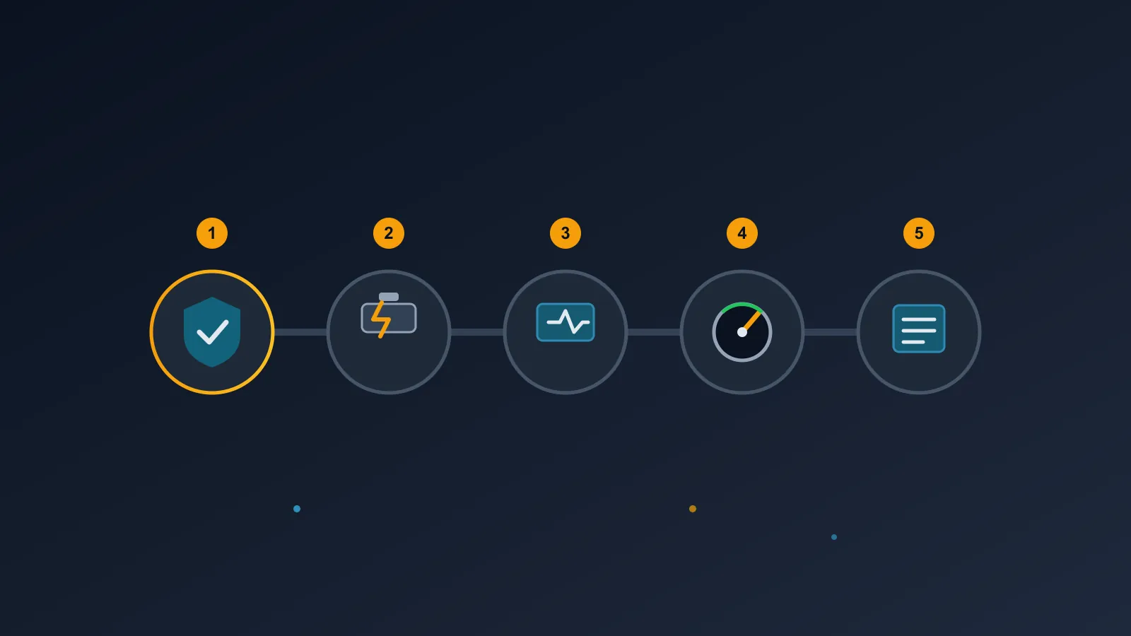
- Make the area safe — Electrically isolate the generator, reset emergency stop switches, verify circuit breaker status, and inspect the enclosure for active fuel, coolant, or oil leaks.
- Check simple causes first — Test resting and cranking battery terminal voltage, verify the battery disconnect switch is ON, check fuel tank levels, and bleed air from low-pressure fuel lines.
- Check output at the terminals — Measure generator terminal voltage and output frequency under no-load; if frequency is below nominal rating, troubleshoot engine speed governance before adjusting voltage parameters.
- Check load and thermal state — Monitor connected load percentages, engine coolant operating temperatures, and lube oil pressures against manufacturer nameplate ratings and ISO 8528 thresholds.
- Escalate with data — Document all active control panel fault codes, physical symptoms, and multimeter readings; escalate complex internal engine repairs, injector calibrations, and load bank purging to certified service technicians.
The 8 Most Common Diesel Generator Problems at a Glance
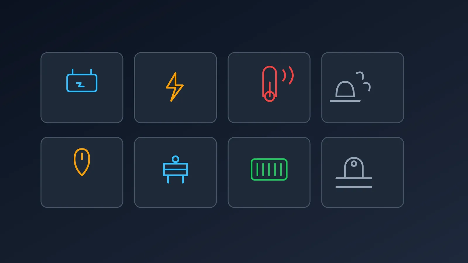
The following 8 operational issues represent the vast majority of field service calls on industrial and commercial diesel standby generators:
- Engine Won’t Start (Starting Failure)
- Low or No Alternator Output Voltage
- Engine Overheating & Thermal Shutdown
- Wet Stacking, Low-Load Fouling & Black Exhaust Smoke
- Abnormally High Fuel Consumption
- Battery Degradation & Standby Charging Failure
- Low Engine Oil Pressure Alarms & Shutdowns
- Air Ingestion in the Fuel Injection System
Diesel Generator Troubleshooting Matrix
The matrix below provides a quick operational reference categorizing each major generator problem, key physical symptoms, underlying root causes, immediate operator quick-checks, and required service intervention levels.
| Problem | Key Symptoms | Common Causes | Operator Quick Check | Fix Level |
|---|---|---|---|---|
| 1. Engine Won’t Start | Cranks but won’t ignite, or complete starter unresponsiveness | Low battery voltage, blown DC control fuse, E-stop active, air in fuel lines | Verify battery disconnect switch is ON, reset E-stop, check battery voltage | Operator / Electrician |
| 2. Low or No Output Voltage | Generator runs at speed but output voltage is zero or below nominal | Loss of residual magnetism, damaged AVR, blown rotating diodes, incorrect MPU gap | Check main output breaker, inspect AVR connections, check MPU gap (~0.8 mm) | Electrician / Technician |
| 3. Engine Overheating | High water temperature (HWT) alarm, coolant venting from overflow | Low coolant level, clogged radiator fins, loose fan belt, restricted room airflow | Inspect coolant level, check fan belt tension (10–12 mm), verify louver airflow | Operator / Technician |
| 4. Wet Stacking & Black Smoke | Dark oily residue leaking from exhaust flange, dense black smoke under load | Continuous operation at <30% load, clogged air filter, delayed injection timing | Check connected electrical load, inspect air filter restriction indicator | Operator / Technician |
| 5. High Fuel Consumption | Rapid fuel depletion, black smoke, reduced engine power | Overloaded engine, dirty air filter, dripping injector nozzles, incorrect valve clearance | Check load percentage, inspect air filter for high restriction (~5 kPa) | Operator / Technician |
| 6. Battery Degradation | Slow cranking, clicking starter solenoid, battery charger fault alarm | Sulphated battery plates, low float voltage, loose/corroded terminals, expired cell life | Check terminal cleanliness, measure resting (≥12.4V/24.8V) and cranking voltage | Operator / Electrician |
| 7. Low Oil Pressure | Low oil pressure (LOP) alarm/shutdown, heavy metallic thumping sound | Low oil level, fuel dilution, incorrect oil viscosity, worn main/rod bearings | Check oil dipstick level, inspect oil for diesel odor, check for external leaks | Operator / Technician |
| 8. Air in Fuel System | Engine surges, misfires, or stalls shortly after starting | Loose fuel line fittings, degraded suction hose, defective fuel check valve | Verify fuel tank level (>30%), operate manual hand primer to bleed air | Operator / Technician |
1. Engine Won’t Start (Starting Failure)

Symptoms
When the control panel triggers a start command, the engine either fails to crank entirely (producing a silent unresponsiveness or a rapid clicking sound at the starter solenoid) or cranks continuously without achieving self-sustaining ignition.
Common Causes
Starting failures are primarily driven by DC control circuit interruptions, low battery terminal voltage, closed fuel shutoff valves, air locks in low-pressure supply lines, or active safety lockouts triggered by the Engine Control Module (ECM). For instance, an advanced Cummins ECM enforces safety protection logic that automatically trips the fuel solenoid if establishing oil pressure is not detected within 10 to 30 seconds of cranking.
Step-by-Step Diagnosis
- Verify DC Control Circuit & Switches: Ensure the local mode selector switch is set to AUTO or MANUAL, and verify that all emergency stop buttons are fully reset. Check DC control circuit fuses and verify that the main battery disconnect switch is in the ON position (disconnect switches should only be turned OFF during long-term storage or maintenance).
- Measure Battery Terminal Voltage: Using a calibrated digital multimeter, test resting terminal voltage across the starting battery bank. For a 12V DC starting system, resting voltage must be ≥12.4V, and cranking voltage under starter load must not drop below ~9.6V. For a 24V DC starting system, resting voltage must be ≥24.8V, and cranking voltage under starter load must remain above ~19.2V (exact thresholds depend on the starter motor’s nameplate voltage rating).
- Inspect Fuel Shutoff Solenoid & Priming: Listen for a distinct metallic "click" from the fuel shutoff solenoid when the start command is issued. If the solenoid energizes but the engine fails to catch, operate the low-pressure fuel hand primer to eliminate trapped air bubbles and verify fuel flow.
- Troubleshoot Starter Solenoid Contacts: If pressing the start button produces a heavy clicking sound without starter rotation, inspect the starter solenoid magnetic contacts for pitting, carbon buildup, or severe voltage drop across battery cable lugs.
Prevention
Implement a weekly inspection program verifying control switch positions, battery voltage levels, and fuel solenoid operation. To understand starting mechanics deeper, consult our technical guides on what might cause a generator not to start, review startup timeframes in how long does it take for a diesel generator to start, and explore high-capacity systems in how do large diesel generators start.
2. Low or No Alternator Output Voltage

Symptoms
The diesel engine starts smoothly and achieves nominal operating RPM, but the generator output panel displays 0 Volts, severely depressed phase voltage (e.g., 50–100V on a 400V nominal system), or unstable, fluctuating terminal voltage under load.
Common Causes
Output voltage issues stem from loss of exciter residual magnetism, a defective Automatic Voltage Regulator (AVR), blown rotating rectifier diodes, blown AVR sensing fuses, or an improperly calibrated Magnetic Pickup Unit (MPU) speed sensor.
Step-by-Step Diagnosis
- Verify Engine Operating Frequency First: Before adjusting voltage settings on the AVR, always measure generator output frequency. Nominal speed is required for voltage build-up (1500 RPM for 50Hz generators; 1800 RPM for 60Hz generators). Modern AVRs feature Under-Frequency Roll-Off (UFRO) protection that deliberately reduces output voltage if engine speed drops below rated RPM to protect the exciter stator from over-excitation.
- Measure Residual Field Voltage: With the generator running at nominal speed, measure AC terminal voltage. A functional brushless alternator without exciter power typically displays a residual voltage between 10V and 40V AC generated by residual field magnetism in the exciter stator core.
- Perform Field Flashing (If Residual Voltage is Lost): If residual voltage reads near 0V, the exciter field must be flashed. Connect a 12V DC battery source in series with a limiting resistor and a blocking diode across the exciter field terminals (+ and −) for 2 to 3 seconds while the generator is running, strictly adhering to the manufacturer’s manual.
- Test Rotating Rectifier Diodes: Inspect the rotating diode bridge assembly located on the main rotor shaft. Use a multimeter on diode test mode to check forward and reverse resistance across all six diodes; healthy diodes display a forward voltage drop of ~0.5V to 0.7V and infinite reverse resistance.
- Inspect and Adjust MPU Sensor: Check the Magnetic Pickup Unit (MPU) installed over the engine flywheel ring gear. Verify an MPU probe gap of approximately 0.8 mm (achieved by threading the sensor in until it lightly touches a gear tooth, then backing it off 1/16 to 1/2 turn). Clean iron filings off the magnetic tip.
Prevention
Avoid storing standby generators for extended periods without quarterly test runs to maintain residual field magnetism. Learn more about managing electrical demands in our guide on what is load on a diesel generator.
3. Engine Overheating & Thermal Shutdown
Symptoms
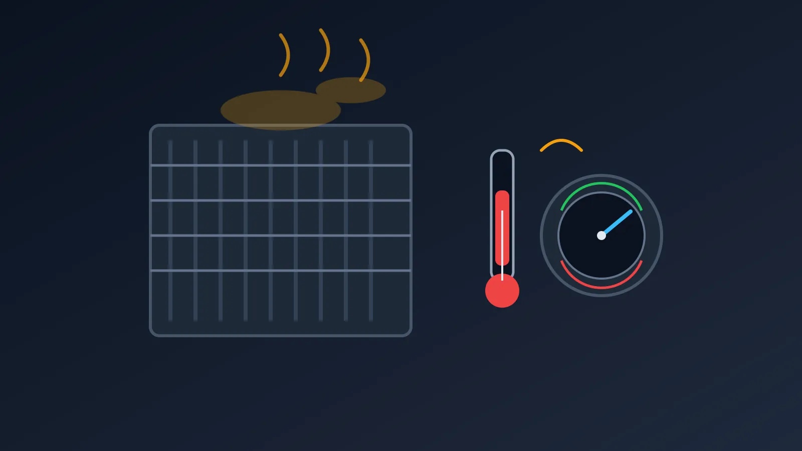
The generator control panel registers a High Water Temperature (HWT) pre-alarm or initiates an automatic safety shutdown as coolant temperature exceeds safe operating thresholds. Coolant may be observed venting from the expansion tank pressure cap, accompanied by a strong glycol odor.
Common Causes
Overheating is caused by insufficient coolant fluid, clogged radiator core fins, loose fan drive belts, a stuck thermostat, water pump impeller failure, or inadequate engine room ventilation and excessive intake/discharge static pressure.
Step-by-Step Diagnosis
- Monitor Temperature Thresholds: Normal engine operating coolant temperature ranges between 82°C and 90°C (180°F–194°F). A HWT pre-alarm typically triggers at ~95°C (203°F), while an automatic emergency shutdown is enforced between 100°C and 105°C (212°F–221°F).
- Inspect Coolant Fluid & External Leaks: Allow the engine to cool completely before inspecting the expansion tank fluid level. Check radiator hoses, water pump weep holes, and jacket water heater fittings for crystalline glycol leaks or hardening.
- Check Fan Belt Tension & Radiator Core: Measure drive belt deflection by applying firm thumb pressure midway between pulleys; correct deflection is 10 mm to 12 mm (3/8" to 1/2"). Inspect the radiator matrix for external dirt, oil mist, or debris restricting airflow.
- Verify Engine Room Ventilation & Static Pressure: Ensure intake louvers and discharge ducts supply adequate airflow CFM. Room ventilation static pressure drop must be calculated and verified against ASHRAE guidelines and manufacturer installation manuals. Radiators are typically rated for 40°C or 50°C ambient cooling capability.
- Check for Thermal Distortion (Perkins 1100 Series Field Note): On engines featuring aluminum cylinder heads (such as the Perkins 1100 Series), severe thermal overheating is a known field issue that can warp the cylinder head mating surface. Per manufacturer guidance, always inspect cylinder head flatness using a precision straightedge and feeler gauge following any major overheating event before installing a replacement head gasket.
Prevention
Keep radiator core fins clean and replace coolant per the engine manufacturer’s schedule (commonly every 2 years or 2,000 operating hours). For details on thermal stabilization, read how long does it take for a generator to cool down.
4. Wet Stacking, Low-Load Fouling & Black Exhaust Smoke

Symptoms
Dark, oily liquid leaks from exhaust piping joints, turbocharger flanges, and silencer drain plugs. The engine produces dense black or dark grey exhaust smoke, experiences sluggish throttle response, and shows heavy soot buildup around exhaust valves.
Common Causes
Wet stacking is primarily caused by continuous generator operation at light electrical loads—specifically below 30% of nameplate rated capacity. Under low-load conditions, cylinder combustion temperatures and pressures are insufficient to expand piston rings fully against cylinder liners, allowing unburnt diesel fuel and lube oil to escape into the exhaust manifold. Other contributing factors include restricted air filters, excessive exhaust backpressure, fuel injector atomization failure, and regional fuel quality variations (such as Indonesia’s transition to B40/B50 biodiesel causing injector deposits or Middle East high-temperature rubber hose degradation).
Step-by-Step Diagnosis
- Evaluate Electrical Operating Load: Check active generator KW / KVA load against rated nameplate capacity. If the unit operates continuously below 30% load, wet stacking will inevitably occur.
- Measure Exhaust System Backpressure: Install a manometer at the exhaust piping test port. Verify that total exhaust restriction does not exceed the engine manufacturer’s maximum allowable backpressure limit—typically ~3.3 kPa (13.2 inches H₂O).
- Diagnose Exhaust Smoke Color: Use the smoke-color reference below to map exhaust characteristics to internal engine mechanisms.
- Execute Load Bank Purging Protocol: To resolve wet stacking, connect a mobile resistive load bank and operate the generator set at ≥70% to 100% rated load for 2 to 4 consecutive hours. The elevated cylinder temperatures burn off unburnt fuel gel, carbon deposits, and cylinder liner varnish.
Exhaust Smoke Color Reference
| Exhaust Color | Thermodynamic & Physical Mechanism | Core Affected Components | Corrective Action |
|---|---|---|---|
| Black Smoke | Incomplete combustion from a fuel-rich mixture, restricted air intake, or atomization failure | Air filter element, fuel injectors, turbocharger, intercooler | Clean/replace air filter, check turbo boost pressure, test injector spray pattern |
| White Smoke | Unburnt fuel droplets or coolant vapor entering combustion chamber due to low cylinder temp | Glow plugs, cold-start timing, cylinder head gasket, fuel timing | Inspect preheating grid, calibrate injection timing, test head gasket sealing |
| Blue Smoke | Engine lubricating oil burning in combustion chamber due to ring or seal bypass | Piston rings, cylinder liners, valve stem seals, turbo oil seals | Measure crankcase blow-by pressure, inspect turbo shaft seals, replace worn rings |
Prevention
Size generators accurately to avoid chronic low-load operation. Learn more about managing smoke issues in what would cause a diesel generator to emit black smoke and understanding load factors in what is load on a diesel generator.
5. Abnormally High Fuel Consumption
Symptoms
The generator consumes significantly more fuel per operating hour than specified on the manufacturer’s performance curve, accompanied by reduced power output, elevated exhaust gas temperatures, and dark exhaust emissions.
Common Causes
High fuel consumption results from operating the generator far outside its peak efficiency envelope, air intake restrictions, fuel injector nozzle wear, retarded fuel injection timing, incorrect valve lash clearances, or internal engine drag.
Step-by-Step Diagnosis
- Compare Consumption Against 75% Load Benchmark: Generator fuel economy is standardized around a 75% rated prime load benchmark, which represents the optimal fuel-to-kilowatt conversion efficiency window (typically 70%–80% load). Operating continuously at 25% load or 110% overload significantly degrades brake specific fuel consumption (BSFC).
- Inspect Air Filter Restriction: Inspect the air filter restriction indicator on the intake housing. A clogged filter creates intake vacuum restriction exceeding the typical allowable limit of ~5 kPa (20 inches H₂O), starving cylinders of oxygen and causing incomplete fuel combustion.
- Test Injector Spray Atomization: Remove fuel injectors and test them on a nozzle pop-tester. Verify nozzle opening pressure, chatter sound, and spray atomization pattern; dripping or misting nozzles dump excess uncombusted fuel into the cylinder.
- Calibrate Injection Timing & Valve Lash: Verify static and dynamic fuel pump injection timing against engine timing marks, and check intake/exhaust valve clearances per manufacturer specifications.
Prevention
Maintain intake air filtration integrity and operate units within their 70%–80% sweet spot. Explore fuel economy metrics further in which is the most efficient diesel generator.
6. Battery Degradation & Standby Charging Failure
Symptoms
When a weekly automatic start test occurs, the engine cranks sluggishly or produces a rapid clicking from the starter magnetic solenoid. The battery charger signals an under-voltage fault, and battery cell tops show white crystalline crusting.
Common Causes
Lead-acid starting batteries degrade due to plate sulphation, electrolyte loss from continuous float overcharging, loose or oxidized cable terminals, or complete cell failure. Some configurations have no float charger at all, or a low-quality charger that under- or over-charges the battery.
Step-by-Step Diagnosis
- Adhere to Health-Based Replacement Standards: While starting batteries have a typical service lifespan of 24 to 36 months, replacement must always be determined by voltage and Cold Cranking Amps (CCA) conductance testing—never solely by calendar age regardless of condition.
- Verify Trickle Charger Voltage: Measure float voltage across battery terminals using a calibrated multimeter. Standard float voltage must be maintained between 13.5V and 13.8V for a 12V system, and 27.0V to 27.6V for a 24V system.
- Conduct Battery Health Threshold Test: Compare measured battery parameters against the threshold matrix below.
- Maintain Long-Term Storage Protocol: For standby units in extended storage, enforce three mandatory rules: run weekly exercise cycles, maintain continuous float charging, and keep the main battery disconnect switch OPEN during non-standby maintenance.
Battery Voltage Threshold Matrix
| Battery State | 12V System | 24V System | Recommended Action |
|---|---|---|---|
| Fully Charged / Healthy | >12.6V resting / >9.6V cranking | >25.2V resting / >19.2V cranking | Battery healthy; clean terminals and maintain float charge |
| Serviceable | 12.4V – 12.6V resting | 24.8V – 25.2V resting | Recharge/equalize; verify charger output and AC supply |
| Action Required | 12.2V – 12.4V resting | 24.4V – 24.8V resting | Recharge and retest; inspect charger and parasitic loads |
| Failed | <12.2V resting / <9.6V cranking | <24.4V resting / <19.2V cranking | Replace battery; confirm CCA <80% nameplate |
Prevention
Keep a quality float charger connected and verify its AC supply; check terminal torque and apply protective grease quarterly; test cranking voltage monthly. Replace starting batteries on a normal 24–36 month cycle, or sooner if voltage/CCA testing shows failure. Flooded lead-acid batteries need periodic electrolyte top-up, while maintenance-free (MF/AGM/GEL) types do not.
7. Low Engine Oil Pressure Alarms & Shutdowns

Symptoms
The generator control panel activates a Low Oil Pressure (LOP) warning or executes an immediate safety shutdown. The engine may exhibit elevated operating noise, including heavy metallic knocking from the lower crankcase.
Common Causes
Low oil pressure is triggered by insufficient oil levels, fuel dilution of lube oil, incorrect oil viscosity, clogged oil filter bypass valves, defective oil pressure senders, worn oil pump gears, or excessive clearances in crankshaft main and connecting rod bearings.
Step-by-Step Diagnosis
- Verify Pressure Thresholds: Typical oil pressure operating parameters (refer to specific engine manual) are: idle pressure < ~1.5 bar (22 psi) triggers pre-alarm; normal operating pressure ranges between 3.0 bar and 4.5 bar (43.5–65 psi).
- Inspect Oil Dipstick & Fuel Dilution: Check dipstick oil level and inspect fluid consistency. If the oil level is abnormally high and smells strongly of diesel fuel, unburnt fuel is diluting the oil, severely lowering viscosity and oil film strength.
- Check Perkins 1000 Series Front Cover (Field Note): On Perkins 1000 Series (Phaser) engines, internal corrosion of the front timing gear cover plate is a known issue that allows coolant and engine oil to mix directly inside the timing gear housing. This creates a milky oil-coolant emulsion in the oil pan that is frequently misdiagnosed as a cylinder head gasket failure.
- Adhere to Oil Change Intervals & API/SAE Standards: Replace lubricating oil and full-flow filters every 250 to 500 operating hours or annually. Use high-grade heavy-duty diesel oils meeting API CI-4, CJ-4, or CK-41 standards, with SAE 15W-40 viscosity for warm/tropical ambient environments.
Prevention
Regularly sample lube oil for spectrographic wear metal analysis. Learn more about oil capacities in how much oil does a generator take and automatic shutdown triggers in why does a power generator automatically shut down.
8. Air Ingestion in the Fuel Injection System

Symptoms
The generator engine starts momentarily, then stumbles, surges in RPM, misfires across multiple cylinders, and stalls completely. Operating the manual priming pump feels soft and spongy.
Common Causes
Air ingestion occurs when suction-side fuel lines, water separator gaskets, or fuel filter O-rings develop micro-leaks, drawing air into the low-pressure fuel circuit.
Step-by-Step Diagnosis
- Verify Fuel Tank Level: Ensure fuel tank level remains above ≥30% capacity to prevent fuel pickup tubes from drawing air during sloshing or baseline suction.
- Operate Hand Primer on Low-Pressure Side: Loosen the air bleed screw on the primary fuel filter housing. Pump the manual hand primer until clear, bubble-free fuel flows out. Note that hand primers only purge the low-pressure supply circuit; high-pressure fuel line bleeding must be performed by certified technicians.
- Inspect Check Valves & Middle East Hose Degradation: Verify the operation of the non-return check valve (anti-siphon valve) to prevent fuel from draining back into the tank during shutdown. In high-ambient regions such as the Middle East, inspect rubber fuel supply hoses for heat hardening and vacuum collapse, replacing them on a scheduled basis.
Prevention
Keep suction-side fittings tight and replace aged hoses on schedule; fit a one-way check valve on the suction line; always bleed the system after a filter change; in hot climates, inspect hoses more frequently and replace before heat hardening causes vacuum collapse.
How to Prevent Diesel Generator Failures: 5 Operational Protocols

To address the most common issues with diesel generators and how to avoid them, plant owners and facility managers should enforce five standard operational protocols:
- Regular Load Testing2: Conduct monthly operational test runs under ≥70% rated load for at least 1 hour. Short no-load startup checks (10–15 minutes) are acceptable for verifying control circuit and starter responsiveness, but they cannot replace load testing and will not prevent wet stacking.
- Proactive Battery Maintenance: Maintain continuous float charging, perform monthly terminal cleaning, and conduct battery CCA conductance tests periodically (e.g., every 6 months). Plan replacement around 24–36 months, and replace immediately if CCA falls below 80% of nameplate.
- Strict Fluid & Fuel Quality Standards: Use manufacturer-approved heavy-duty coolants enriched with Supplemental Coolant Additives (SCA), API CK-4/CJ-4 15W-40 lubricating oil, and clean diesel fuel compliant with regional bio-blend standards (such as B40/B50 protocols).
- Compliance with ISO 85283 Duty Ratings: Operate generator sets strictly within their design duty application: Emergency Standby Power (ESP ≤ 200 hours/year), Prime Power (PRP unlimited hours with 10% overload capability), Limited-Time Power (LTP ≤ 500 hours/year), or Continuous Power (COP constant base load).
- Engine Room Ventilation & Hose Replacement: Maintain radiator cooling designs for 40°C or 50°C ambient temperatures, inspect intake louver free-area, and replace all rubber coolant and fuel hoses every 3 to 5 years.
Review complete maintenance schedules in diesel generator maintenance schedule and operational routines in how to check a diesel generator.
Frequently Asked Questions (FAQ)
What is the most common diesel generator problem?
The single most common diesel generator problem is starting battery failure caused by terminal corrosion, plate sulphation, or depleted float charge. Regular battery testing prevents most starting failures, and batteries should be replaced when voltage or CCA testing shows failure, typically after 24 to 36 months.
How do I reset a diesel generator after a fault shutdown?
To reset a generator after a safety shutdown, first identify and rectify the underlying fault (e.g., low oil level or high coolant temperature). Clear the fault code on the digital control panel, then press the RESET button before selecting AUTO mode.
Why does my diesel generator turn off after running for a few minutes?
A generator shutting down after several minutes typically triggers a safety protection parameter, such as low oil pressure, high water temperature, low coolant level, or an ECM safety lockout due to an unacknowledged sensor fault.
What causes wet stacking in a diesel generator?
Wet stacking is caused by operating a diesel generator continuously under light electrical loads below 30% of nameplate capacity. Unburnt fuel and soot condense in the exhaust manifold, creating dark oily leaks and carbon buildup.
How often should a standby diesel generator be tested?
Standby diesel generators should undergo a brief weekly or bi-weekly functional test, accompanied by a monthly operational test under at least 70% rated load for 1 hour to maintain engine temperature, clear moisture, and verify cooling performance.
Can running a generator continuously damage the engine?
Continuous generator operation does not cause damage provided the unit is correctly sized for the load, operated within its ISO 8528 duty rating (Continuous or Prime power), and serviced with scheduled oil, filter, and coolant renewals. For round-the-clock facility usage and shutdown protocols, read our guide on whether generators need to be turned off overnight.
What causes a diesel generator to hunt or surge in RPM?
RPM hunting or surging is caused by air trapped in fuel lines, dirty fuel filters, an improperly adjusted governor PID gain setting, a sticking fuel pump actuator, or an incorrect Magnetic Pickup Unit (MPU) sensor gap.
How do I know if my generator’s AVR is faulty?
A faulty Automatic Voltage Regulator (AVR) is indicated by zero output voltage during nominal engine speed, severe voltage fluctuations under constant load, uncontrollable over-voltage, or blown AVR power input fuses.
Methodology & E-E-A-T Disclosure
Technical Methodology & Field Standards
The diagnostic procedures and technical metrics presented in this guide are synthesized from international field engineering standards, including ISO 8528-1~5 (Reciprocating internal combustion engine driven alternating current generating sets), NFPA 1104 (Standard for Emergency and Standby Power Systems), SAE J19955 engine power standards, API oil classifications, and official technical service documentation from major OEM engine and alternator manufacturers.
Engineering Advisory
This technical guide is published by H&C Diesel Generator Manufacture for educational and engineering support purposes. Equipment specifications, operational tolerances, and wiring schematics vary by model; always consult the official manufacturer service manual before executing repairs. For procurement, compare our Diesel Generator Buying Guide before selecting a set.

-
API Engine Oil Licensing & Certification System (EOLCS): Why this source is cited: the article names API CI-4, CJ-4 and CK-4 service categories for lubricating oil; this official API page lets readers verify that each category is current and what operating conditions it covers. ↩
-
NFPA 70B, Standard for Electrical Equipment Maintenance: Why this source is cited: the prevention protocol recommends monthly load testing; NFPA 70B is the electrical-maintenance standard that underpins the testing and inspection cadence recommended in this section. ↩
-
ISO 8528-1:2018, Application, ratings and performance: Why this source is cited: the prevention section quotes ESP/PRP/LTP/COP runtime limits; ISO 8528-1 is the rating standard that defines these duty classes, so readers can verify the boundaries quoted here. ↩
-
NFPA 110, Standard for Emergency and Standby Power Systems: Why this source is cited: the methodology cites NFPA 110 for emergency and standby power systems; the official NFPA page is the source for the installation, testing and maintenance requirements referenced in this guide. ↩
-
SAE J1995, Engine Power Test Code: Why this source is cited: the methodology cites SAE J1995 for engine power ratings; this standard defines how gross engine power is measured, which matters when comparing the kW figures quoted by different OEMs. ↩