
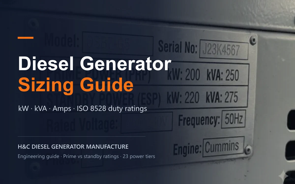
Diesel generator sizing is the engineering process of matching a generator’s kVA rating to a facility’s total load, motor starting inrush and required ISO 8528 duty rating (PRP vs ESP). Calculate kW ÷ power factor for kVA, verify current and starting surge, then apply a consultant-approved margin of 10%–25%.
Key takeaways
- Size in kVA, not kW alone — divide total kW by the load power factor (typically 0.80).
- Match the duty rating — PRP for extended outages; ESP for short emergency backup.
- Leave headroom for starting — check motor inrush and keep steady load near 70%–80% for efficiency.
1. Introduction: The High Price of Mis-Sizing
In commercial, industrial, and institutional operations, electrical power availability is not merely a utility requirement—it is a core operational foundation. Selecting a commercial diesel generator set requires precise application engineering. Relying on superficial load estimates or rule-of-thumb guesswork introduces systemic vulnerabilities that carry severe financial and operational penalties.
Key Sizing Risks at a Glance:
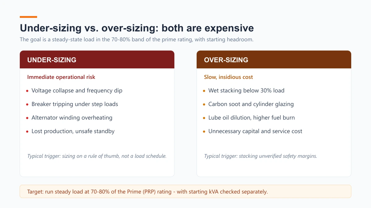
- Undersizing Risks: Immediate voltage collapse, transient frequency decay, total load rejection, nuisance circuit breaker tripping, and generator winding insulation breakdown under thermal overload.
- Oversizing Risks: Sustained light-load operation (<30% load factor), exhaust wet stacking, unburned fuel soot accumulation, cylinder wall glazing, lube oil dilution, and elevated Total Cost of Ownership (TCO).
Undersizing a diesel generator set creates immediate operational failure risks. When connected electrical loads exceed the alternator’s kVA rating or the engine’s kilowatt output, the generating set experiences transient frequency decay and severe voltage dips. Under heavy step loads, this can lead to total load rejection, nuisance circuit breaker tripping, and potential insulation breakdown in alternator windings due to thermal overload. In mission-critical environments such as hospitals, data centers, and manufacturing plants, unexpected power collapse translates directly into unbudgeted downtime, equipment damage, and compromised safety.
Conversely, oversizing a generator set creates an insidious, long-term operational trap. Diesel engines are internal combustion machines engineered to operate under substantial thermal and mechanical loading. Running a generator continuously below 30% of its rated capacity leads to a condition known as wet stacking. At low load factors, cylinder combustion temperatures drop below optimal levels, preventing complete fuel atomization and piston ring expansion. Unburned diesel fuel, carbon soot, and condensed oil accumulate inside the exhaust manifold and turbocharger housing. Over extended periods, this causes cylinder wall glazing, lube oil dilution, excessive oil consumption, and premature engine overhaul requirements. Furthermore, an oversized unit operates far outside its optimal Brake Specific Fuel Consumption (BSFC) curve, driving up total cost of ownership.
Achieving the correct generator size requires balancing transient motor starting capabilities with long-term fuel efficiency and engine longevity. This comprehensive guide outlines the technical principles, mathematical formulas, rating standards, and engineering workflows necessary to specify the right commercial diesel generator for your facility.
2. Fundamental Electrical Parameters & Conversion Formulas
Quick formulas
- kVA = kW ÷ Power Factor
- Amps (3-phase) = kVA × 1000 ÷ (1.732 × Voltage)
- Amps (single-phase) = kVA × 1000 ÷ Voltage
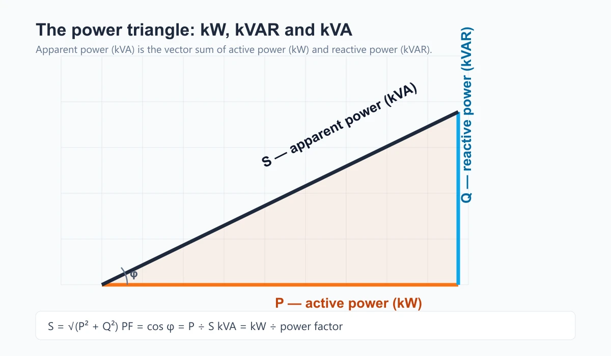
Accurate generator sizing requires a thorough understanding of basic electrical engineering parameters. In alternating current (AC) power systems, generator capacity is expressed in two distinct units: kilowatts (kW) and kilovolt-amperes (kVA). The relationship between these two metrics is governed by the power factor (PF).
- Active Power (kW): Represents real work performed by connected equipment (heat, light, mechanical shaft rotation).
- Apparent Power (kVA): Represents the total vector sum of active power (kW) and reactive power (kVAR). Alternators must be physically dimensioned for total kVA.
- Power Factor (PF): The ratio of active power to apparent power (PF = kW ÷ kVA).
Standard commercial and industrial three-phase diesel generator sets are rated by international conventions at a lagging power factor of 0.80. To calculate the required generator apparent power in kVA from a known active load in kW, apply the following conversion formula:
kVA = kW ÷ Power Factor
For example, a facility with a 100 kW active load operating at a standard 0.80 power factor requires an alternator capacity of:
kVA = 100 kW ÷ 0.80 = 125 kVA
To determine the full-load operating current in Amperes (Amps) for three-phase AC systems, use the standard three-phase current equation:
Amps (3-phase) = kVA × 1000 ÷ (1.732 × Voltage)
Where kVA is apparent power, Voltage is line-to-line voltage in Volts, and 1.732 is the square root of 3.
For single-phase AC systems, the current equation simplifies to:
Amps (single-phase) = kVA × 1000 ÷ Voltage
When sizing equipment, engineers must never mix single-phase and three-phase voltage variables. At an identical kVA capacity, a single-phase system draws approximately three times the current of a balanced three-phase system. For a comprehensive analysis of system load profiles, refer to our detailed guide on understanding electrical load on a diesel generator.
Different electrical loads exhibit widely varying power factor characteristics. The table below lists typical power factor values across common commercial and industrial equipment categories, adapted from practical electrical engineering guidelines documented in the Electrical Installation Guide1.
| Equipment Load Type | Typical Power Factor (PF) | Operational Characteristics & Sizing Impact |
|---|---|---|
| Resistive Heating & Incandescent Lighting | ≈1.00 | Pure active load; active power kW equals apparent power kVA. |
| Full-Load Electric Motors (Pumps, Fans, Compressors) | 0.70–0.85 | Inductive load; requires reactive power for magnetic excitation. |
| Light-Load / No-Load Electric Motors | 0.20–0.30 | Extremely low PF; high reactive kVAR draw relative to low kW output. |
| HVAC & Commercial Refrigeration Compressors | 0.70–0.85 | Mixed inductive load; subject to frequent dynamic cyclic starting. |
| Fluorescent Lighting (Magnetic Ballasts) | 0.50–0.60 | Low PF; produces current distortion requiring power factor correction. |
| LED Lighting Systems (Electronic Drivers) | 0.50–0.90 | Varies by driver quality; high-end commercial drivers include active PFC. |
| Industrial Arc Welders | 0.40–0.60 | Highly inductive, intermittent step load; causes severe voltage fluctuation. |
| UPS Systems & VFDs (With Active PFC) | 0.90–0.99 | High displacement PF, but non-linear harmonic current distortion. |
| UPS Systems & VFDs (Without Active PFC) | 0.60–0.80 | Non-linear load; introduces harmonic heating in alternator rotors. |
3. Generator Power Ratings & The Quoting Pitfall (ISO 8528 Breakdown)
A frequent point of confusion in commercial generator procurement is the distinction between operational customer terminology and official manufacturing rating standards. Commercial buyers often describe their application as “backup power” or “prime power,” but generator sets are engineered and certified under the international standard ISO 8528-1.
Commercial Customer Terminology vs. ISO 8528 Technical Ratings
From an operational standpoint, commercial buyers categorize generator requirements into four primary service profiles:
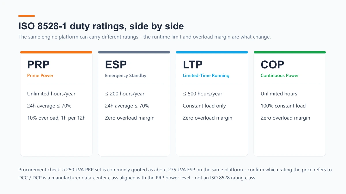
- Prime Power (PRP): Required for facility operations where utility grid power is unavailable, unreliable, or subject to frequent, extended outages (such as daily operations lasting up to 12 hours per day). Under ISO 8528-1, a Prime Power (PRP) unit is designed to supply variable electrical load for an unlimited number of annual operating hours. Crucially, a genuine ISO 8528 PRP rating permits a 10% overload capability for 1 hour within every 12 hours of continuous operation. The permissible 24-hour average power output shall not exceed 70% of the PRP rating.
- Emergency Standby Power (ESP): Intended solely for supplying emergency electrical power during unexpected utility grid failures. Under ISO 8528-1 specifications, an Emergency Standby Power (ESP) rating is defined for variable load applications with annual operating time capped at 200 hours per year. Most importantly, an ESP rating carries zero overload capability. The permissible 24-hour average power output shall not exceed 70% of the ESP rating.
- Limited-Time Running Power (LTP): Intended for limited-duration supply (up to 500 hours per year) at a constant load, with zero overload capability.
- Continuous Operating Power (COP): Specified for base-load utility applications where the generator set operates at 100% constant load for 24 hours a day, 365 days a year without interruption (such as power generation plants or combined heat and power installations). COP units have zero overload capability.
Additionally, manufacturers specify Data Center Continuous (DCC/DCP) ratings. DCC/DCP is not an ISO 8528 rating class; it is a manufacturer classification developed specifically for data-center applications. Its power level is aligned with the ISO 8528 PRP rating, but it permits continuous operation at a 100% average load factor. Confirm the exact rating basis directly with the manufacturer.
For further insights into continuous operating limits and maintenance intervals, refer to our technical guide on how long a diesel generator can run continuously.
The “Emergency Application” Misconception
A critical pitfall in B2B generator selection is confusing application intent with ISO rating mechanics. Facility buyers frequently assume: “My generator is only for emergency backup during power outages, so I should buy an ESP-rated generator.”
This reasoning is dangerous in regions with fragile electrical grids, severe weather vulnerabilities, or long outage restoration windows. An emergency utility outage in an industrial zone may last 12 to 48 continuous hours. If a buyer specifies a generator based on an ESP rating, running that engine continuously under heavy load during a prolonged multi-day outage exceeds its design limits. Because an ESP rating allows no overload margin and assumes short, intermittent runtime, continuous operation can trigger engine thermal overload, high coolant temperature alarms, automatic shutdown, and potential warranty voiding. If extended power interruptions are possible, the unit must be specified at a Prime Power (PRP) rating—even if its primary commercial purpose is emergency backup.
The 10% Quoting Trap
In the commercial generator marketplace, a widespread quoting trap stems from the mathematical relationship between ESP and PRP ratings on identical engine-alternator platforms. On many engine-alternator platforms, the manufacturer’s ESP rating is commonly about 10% higher than its PRP rating (manufacturer-dependent):
ESP ≈ PRP × 1.10 (typical, manufacturer-dependent)
For example, a heavy-duty industrial diesel engine platform rated at 250 kVA PRP is simultaneously rated by the manufacturer at 275 kVA ESP.
Rating Comparison on the Same Engine Platform:
- 250 kVA PRP (Prime Power Rating): Unlimited annual operating hours (24h average ≤70%); 10% overload margin allowed (1 hr in 12 hrs).
- 275 kVA ESP (Standby Power Rating): Maximum 200 hours per year limit (24h average ≤70%); zero overload margin.
Unscrupulous or inexperienced vendors exploit this distinction when competing on price. When a customer requests a quote for a “250 kVA generator for site backup,” a vendor may quote a unit whose ESP rating is 250 kVA—meaning its underlying PRP rating is only 227 kVA (where the 10% spread applies). The vendor presents this smaller engine machine as a “250 kVA unit” at a substantially lower purchase price than competitors quoting a true 250 kVA PRP machine.
When the customer installs this equipment and operates it continuously during an outage, the engine is forced to run at its absolute mechanical limit without any safety headroom. The machine experiences elevated operating temperatures, premature wear, and frequent tripping. Buyers should evaluate suppliers transparently against ISO 8528 definitions, as referenced in technical literature from the Logistics Cluster ISO 8528 Standards Guide2.
| Rating Category | ISO 8528 Code | Typical Application Profile | Annual Runtime Limit | Overload Capacity | Procurement Review Checklist |
|---|---|---|---|---|---|
| Prime Power | PRP | Off-grid, peak shaving, frequent or extended grid outages. | Unlimited hours (24h avg ≤70%). | 10% overload for 1 hr per 12 hrs. | Confirm rating is PRP if continuous operation >6–8 hrs is possible. |
| Emergency Standby | ESP | Pure standby backup with reliable primary utility grid. | Max 200 operating hrs/yr (24h avg ≤70%). | Zero overload capability. | Verify vendor is not quoting ESP to mask an undersized PRP engine. |
| Limited-Time Running | LTP | Constant-load backup for short duration. | Max 500 operating hrs/yr. | Zero overload capability. | Confirm load is constant and runtime capped under 500 hours/year. |
| Continuous Power | COP | Base-load power plant, CHP, constant 100% continuous duty. | Unlimited hours at constant load. | Zero overload capability. | Required only for 24/7/365 constant load power station installations. |
To examine standard product specifications across dedicated emergency configurations, explore our standby diesel generator series.
4. How to Size a Diesel Generator: 5-Step Engineering Process
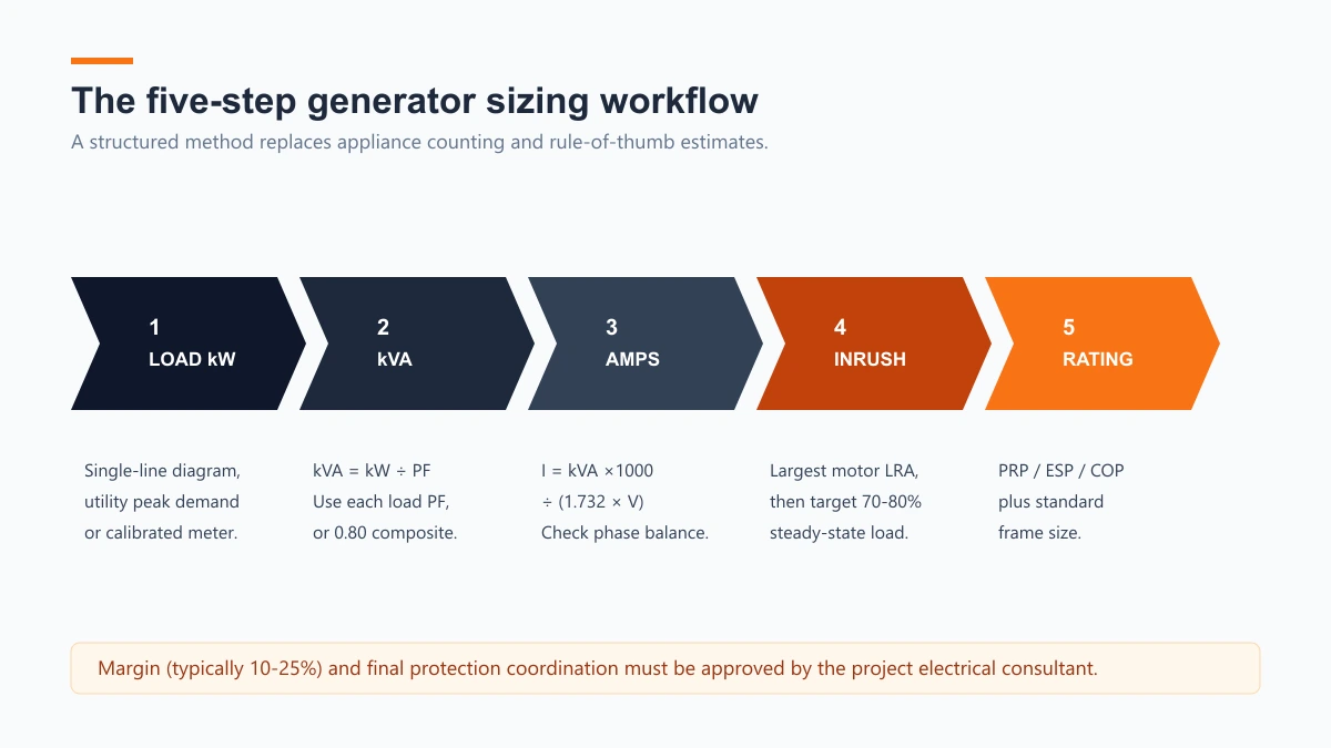
Sizing a commercial diesel generator set requires a structured engineering approach rather than arbitrary load tallying. Follow this systematic five-step methodology to determine the correct generator capacity for your facility.
- Quantify total connected load (kW) — use single-line diagrams or utility peak-demand records.
- Convert to apparent power (kVA) — divide kW by the load power factor.
- Calculate running current — verify voltage and phase characteristics.
- Check motor starting inrush and load factor — target 70%–80% loading; margin set by consultant.
- Select the ISO 8528 rating and frame size — PRP / ESP / COP; match standard frames.
Step 1: Quantify Total Connected Load Demand
Begin by aggregating the total electrical load of the facility. For commercial and industrial sites, this is determined by retrieving electrical engineering single-line diagrams (SLDs), utility billing demand records, or measuring peak current draw using calibrated power quality analyzers. Avoid household-style consumer checklists (“counting appliances”). Record active power in kilowatts (kW_i) or apparent power in kilovolt-amperes (kVA_i) for each major circuit branch, distinguishing between continuous steady-state loads and intermittent equipment loads.
Step 2: Apply Load Power Factors to Calculate Total Apparent Power (kVA)
Convert all active power loads (kW) to apparent power (kVA) using the specific power factor (PF_i) of each load category identified in Section 2:
kVA(total) = sum(kW_i ÷ PF_i)
If individual load power factors are unknown, a conservative composite power factor of 0.80 is standard for mixed industrial facility loads.
Step 3: Calculate Operating Current & Verify Voltage/Phase Characteristics
Determine the total full-load running current (Amps_running) for the system using the appropriate single-phase or three-phase current formula. Verify site utility service voltage (e.g., 400V/230V 3-phase 4-wire, 480V 3-phase, or 208V 3-phase) and operating frequency (50 Hz or 60 Hz). Ensure that phase unbalance across a three-phase generator alternator does not exceed 10% to 15%, as unbalanced single-phase loads induce severe neutral currents and localized rotor heating.
Step 4: Account for Motor Starting Inrush, Optimal Load Factor & Safety Margins
Evaluate dynamic starting impacts and operational margins:
- Motor Starting Surge: Calculate the Locked Rotor Amperes (LRA) of the largest electric motor starting directly on the generator. Ensure the alternator can supply starting kVA (SkVA) without exceeding allowable voltage dip thresholds.
- Optimal Fuel Efficiency Load Factor: Diesel engine fuel efficiency follows an optimal BSFC curve. Generators operate at peak fuel efficiency when running at 70% to 80% (target 75%) of their rated Prime capacity. Sizing a machine to run at a 75% steady-state load factor delivers optimal fuel economy while maintaining headroom for transient step-loads.
- Consultant-Approved Safety Margin: Apply a safety growth margin—typically 10% to 25%—to accommodate future facility expansion and ambient environmental derating. The exact margin must be reviewed and certified by the buyer’s professional electrical consultant.
Step 5: Select Generator Rating & Match Engine-Alternator Series
Combine steady-state kVA, starting kVA, and safety margins to establish the required generator kVA rating. Select an engine-alternator package that meets or exceeds these parameters under the required ISO 8528 duty classification (PRP vs. ESP). For detailed guidance on sizing calculations, refer to technical analysis published by Consulting-Specifying Engineer3.
Worked Engineering Example: Commercial Facility Sizing
To illustrate the 5-step methodology, consider a commercial facility with the following connected electrical load profile:
- Steady-State Facility Base Load: 120 kW (Lighting, office IT, HVAC electronics) at 0.85 PF.
- Industrial Electric Motor: 30 kW (Water pump) operating at 0.80 PF, started via Direct-On-Line (DOL).
- System Voltage: 400V Three-Phase, 50 Hz.
- Required Duty: Prime Power (PRP) for continuous backup during extended grid outages.
Step-by-Step Calculation:
- Calculate Base Load Apparent Power:
kVA(base) = 120 kW ÷ 0.85 ≈ 141.2 kVA - Calculate Motor Steady-State Apparent Power:
kVA(motor) = 30 kW ÷ 0.80 = 37.5 kVA - Total Steady-State System Load:
kW(total) = 120 + 30 = 150 kW
kVA(steady) = 141.2 + 37.5 = 178.7 kVA - Calculate Total Running Current at 400V Three-Phase:
Amps(running) = 178.7 × 1000 ÷ (1.732 × 400) = 178,700 ÷ 692.8 ≈ 257.9 Amps - Evaluate Motor Starting Inrush Impact:
A 30 kW motor started Direct-On-Line (DOL) draws approximately 6 times its rated running current during acceleration (LRA ≈ 6 × Amps_motor_rated).
kVA(motor_start) ≈ 6 × 37.5 kVA = 225.0 kVA
Peak transient starting demand on the generator when the 30 kW motor starts across the running base load:
kVA(peak) = kVA(base) + kVA(motor_start) = 141.2 + 225.0 = 366.2 kVA (transient starting kVA) - Apply Optimal 75% Fuel Factor & Consultant Safety Margin:
To ensure the steady-state operating load of 178.7 kVA sits near the optimal 75% fuel efficiency sweet spot:
Target Generator Rating = kVA(steady) ÷ 0.75 = 178.7 ÷ 0.75 ≈ 238.3 kVA - Final Rating Selection:
Matching this requirement against standard industrial generator output steps leads to selecting a 250 kVA Prime Power (PRP) (or 275 kVA ESP) three-phase diesel generator set. A 250 kVA PRP set is normally capable of supplying a short-duration starting surge of this magnitude within the alternator’s transient capability (typically 2–3× rated current for a few seconds); confirm against the alternator datasheet and acceptable voltage dip while maintaining the steady-state running load at a highly efficient 71.5% load factor.
For detailed specifications on complete industrial generator packages, visit our industrial diesel generator set catalog.
5. Quick Sizing Method: Reverse Calculation from Breaker Amps
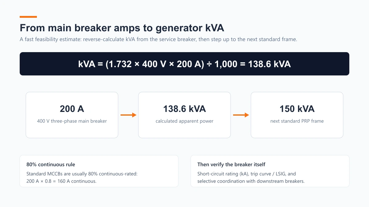
When full equipment load schedules are unavailable during initial feasibility studies, plant engineers often estimate generator capacity directly from the main service panel circuit breaker rating.
Amps to kVA Reverse Formula
For a three-phase system, reverse-calculate the maximum apparent power capacity (kVA) from the main circuit breaker current rating (Amps_breaker) using the formula:
kVA ≈ (1.732 × Voltage × Amps_breaker) ÷ 1000
Worked Calculation Example: Consider a facility served by a 200-Amp main circuit breaker on a 400V Three-Phase utility service:
kVA = (1.732 × 400 × 200) ÷ 1000 = 138,560 ÷ 1000 ≈ 138.6 kVA
To select a generator, apply standard manufacturing size increments and select the next higher standard rating step—in this case, a 150 kVA Prime Power generator set.
For quick reference tables on specific circuit ratings, consult our application articles on sizing a generator for 32-Amp circuits and sizing a generator for 200-Amp main service panels.
Beyond Amps: 4 Critical Circuit Breaker Specifications
While reverse calculation from breaker amperage provides a fast initial estimate, engineers must recognize that a circuit breaker is not merely an amperage number. When specifying the main circuit breaker mounted on a diesel generator set, four critical electrical performance parameters must be verified:
- Short-Circuit Breaking Capacity (I_cu / I_cs in kA): During a bolted short-circuit fault, a diesel generator alternator supplies high subtransient short-circuit current governed by its subtransient reactance (X”_d). The generator circuit breaker must possess a short-circuit breaking rating (kA) exceeding the maximum fault current to safely interrupt short-circuit energy without contact welding or arc rupture failure.
- Trip Curve Characteristics & Inrush Withstand (LSIG Electronic Trip Units): Electric motors and transformers draw severe magnetizing inrush current during energization. Standard thermal-magnetic circuit breakers with fixed instantaneous trip curves often cause nuisance tripping during motor starting. Generator main breakers should feature electronic trip units with adjustable Long-time, Short-time, Instantaneous, and Ground-fault (LSIG) settings or specialized Motor-Circuit Protector (MCP) curves.
- Continuous Load Rating (80% Standard vs. 100%-Rated Breakers): Under the US NEC (Article 210/215), standard MCCBs are rated for 80% continuous duty; for international installations refer to IEC 60947-2 operational categories. A standard 200A breaker continuously carries a maximum of 160A. Unless a specialized, fully tested 100%-rated circuit breaker is specified, the reverse calculation must incorporate an 80% continuous rating correction factor.
- Protection Coordination & Selectivity: The generator main circuit breaker must be selectively coordinated with downstream distribution branch breakers. Time-current characteristic (TCC) curves must ensure that a branch circuit fault trips only the localized branch breaker, keeping the main generator breaker closed and preserving power to the rest of the facility.
6. Motor Starting Inrush Current & Electrical Mitigation Strategies
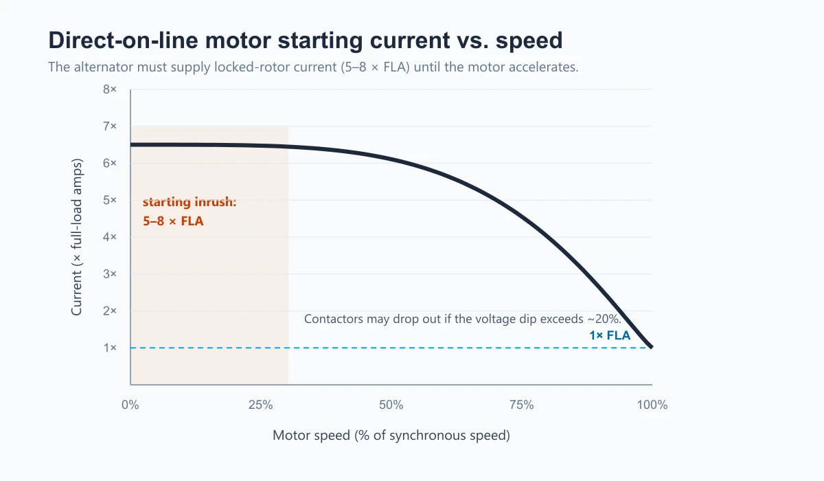
In commercial and industrial facilities, electric motors represent the most demanding transient load imposed on a diesel generator set. Understanding motor starting physics is essential to prevent severe voltage dips and system instability.
Motor Inrush Characteristics:
- Inrush Current Peak: 5x to 8x Full Load Amperes (FLA) during Direct-On-Line (DOL) starting.
- Inrush Power Factor: Extremely low lagging power factor (0.20–0.30).
- Allowable Voltage Dip: Typical limit ~20% (project/standard dependent) maximum transient voltage drop to prevent contactor dropout.
Motor Inrush Physics & Starting kVA (SkVA)
When an AC induction motor starts directly across the line, the motor acts temporarily as a shorted transformer. Before the rotor accelerates to operational speed, it draws Locked Rotor Amperes (LRA)—typically 5 to 8 times its full-load running current (FLA)—at an extremely low power factor (0.20 to 0.30 lagging).
This sudden surge of reactive power creates an instantaneous starting kVA (SkVA) demand on the alternator. The resulting severe current draw causes a transient voltage dip across the alternator windings. If the dip is typically beyond ~20% (project/standard dependent), magnetic contactors in motor starters may drop out (chatter), digital controllers reset, and accelerating torque collapses, causing the motor to stall.
Motor Starting Methods & Generator Capacity Reduction
Engineers can dramatically reduce generator starting kVA requirements by employing reduced-voltage starting technologies. The table below compares common motor starting methods, starting current multipliers, and their impact on generator sizing, incorporating engineering guidelines published by the Electrical Engineering Portal4.
| Motor Starting Method | Inrush Current Multiplier (× FLA) | Starting kVA Reduction | Generator Sizing Impact |
|---|---|---|---|
| Direct-On-Line (DOL) | 5.0–8.0 × FLA | 0% (Full Inrush) | Requires maximum generator alternator headroom to limit voltage dip. |
| Star-Delta (Y-Δ) Starter | 2.5–3.0 × FLA | ≈66% Reduction | Substantially reduces starting kVA; suitable for low-starting-torque loads. |
| Solid-State Soft Starter | 2.0–3.0 × FLA | 60%–70% Reduction | Controlled ramp-up; limits inrush current while preserving acceleration. |
| Variable Frequency Drive (VFD) | 1.0–1.5 × FLA | 80%–90% Reduction | Eliminates starting inrush; introduces non-linear harmonic distortion. |
While Variable Frequency Drives (VFDs) virtually eliminate motor starting inrush, their electronic switching components draw non-linear harmonic currents. Harmonic currents cause heating in alternator rotors and distort voltage waveforms. When powering significant VFD loads, engineers must specify alternators equipped with 2/3 pitch windings, anti-harmonic isolation, and enhanced excitation systems (such as Permanent Magnet Generators, PMG).
For a deep dive into transient starting reactance and generator voltage stability, read our technical article on how motor inrush current affects generator sizing.
Advanced System Engineering Mitigation
Beyond soft starters and VFDs, facility designers implement three system-level engineering techniques:
- Sequential Motor Starting: Programming Programmable Logic Controllers (PLCs) or building management systems to stagger motor starting sequences. Starting the largest motor first allows the generator to absorb initial inrush before subsequent step-loads are energized.
- Automatic Load Shedding: Configuring Automatic Transfer Switches (ATS) to temporarily shed non-essential loads (such as electric water heaters or comfort HVAC) during motor acceleration, reintroducing them once steady-state speed is reached.
- Battery Energy Storage System (BESS) Hybrid Integration: Integrating a small BESS with a digital microgrid controller. The battery system injects high transient current during initial motor starting, allowing the diesel generator set to be sized strictly for steady-state running loads.
7. Application & Industry Sizing Index
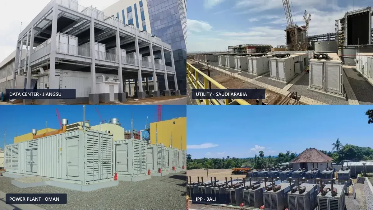
Commercial and industrial facilities present distinct electrical profiles. Use this application index to locate engineering guidelines and real-world project benchmarks tailored to your specific industry sector.
7.1 Industry Application Index
Different commercial sectors exhibit distinct electrical load characteristics, operational tolerances, and regulatory standards. The table below outlines typical capacity benchmarks, rating bases, and critical engineering parameters across major commercial and industrial sectors, referencing documented real-world project installations.
| Industry Sector | Typical Capacity Range | Typical Rating Basis* | Primary Sizing & Reliability Focus | Reference Case Study / Detailed Engineering Guide |
|---|---|---|---|---|
| Data Centers & AI Computing | 1,000 kW – 3,000 kW+ | DCC/DCP (aligned with PRP) | ISO 8528 G3 transient response; N+1 redundancy; high non-linear server UPS loads. | Jiangsu Data Center Backup Power Case • Data Center Sizing Guide |
| Hospitals & Medical Centers | 200 kVA – 1,000 kVA | ESP (NFPA 110 Type 10) / Mission-Critical PRP | NFPA 110 compliance; 10-second fast starting; hospital-grade sound attenuation. | Hospital Emergency Backup Power Case |
| Hotels & Hospitality | 200 kVA – 500 kVA | ESP | HVAC simultaneous load diversity factor; central hot water; guest elevator starting. | Sheraton Hotel Backup Power Case • 72-Room Hotel Generator Sizing Guide |
| Telecom Towers & Hubs | 10 kVA – 100 kVA | PRP / ESP | Weatherproof outdoor enclosures; remote telemetry; ultra-reliable continuous backup. | Telecom Tower Remote Backup Power Case |
| Mining & Quarry Extraction | 500 kW – 1,500 kW | Heavy PRP (continuous) | Heavy continuous Prime duty (PRP); severe dust filtration; crusher motor starting. | Mining Prime Power Station Case |
| Airports & Transit Hubs | 500 kVA – 2,000 kVA | ESP (critical) | Life-safety emergency circuits; runway lighting power quality; low THD requirements. | Airport Emergency Backup Power Case |
| Oil & Gas Drilling Rigs | 500 kW – 1,500 kW | Heavy PRP | ATEX (EU) or Class I, Division 2 (US NEC) options; heavy continuous prime load; mud pump inrush. | Syria SPC Oil Rig Prime Power Case |
| Commercial Real Estate | 100 kVA – 500 kVA | ESP | Life-safety elevator backup; fire suppression pumps; tenant essential load management. | Commercial Building Backup Power Guide • Office Building Sizing Guide • Land Bank Backup Power Case |
| Manufacturing Facilities | 200 kW – 1,000 kW | PRP / Continuous | Preventing costly production line stoppages; motor starting inrush mitigation. | Industrial Generator Sizing Advantages |
| Construction Sites | 100 kVA – 500 kVA | PRP (mobile) | Mobile trailer-mounted units; crane starting surges; multi-equipment branch loads. | Construction Site Generator Selection Guide |
| Resorts & Eco-Lodges | 100 kVA – 300 kVA | ESP / island PRP | Low acoustic noise footprint; remote grid independence; environmental protection. | Resort Diesel Generator Selection Guide |
| Cold Storage & Freezers | 20 kVA – 100 kVA | ESP / dynamic PRP | Refrigeration compressor Locked Rotor Amperes (LRA); frequent dynamic starting. | Commercial Freezer Generator Sizing Guide |
Typical basis only — confirm with your project electrical consultant. NFPA 110 governs emergency-system testing and restoration (Type 10 = accept load within 10 seconds), not the ISO 8528 rating class; PRP is recommended where utility restoration frequently exceeds 12–24 hours. DCC/DCP is a manufacturer data-center classification aligned with the ISO 8528 PRP power level, not an ISO rating. Heavy continuous industrial loads are commonly specified in kW; commercial standby systems are often specified in kVA to align with service/transformer capacity.
7.2 Standard Generator Capacity Selection Matrix
Select your required generator frame size below to view detailed technical specifications, engine options, physical dimensions, and electrical schematics across our 23 standard commercial power tiers:
| Standard Power Frame Sizes (kW) | Direct Product Specification Links |
|---|---|
| Small Commercial (30 kW – 80 kW) | 30 kW Diesel Generator • 40 kW Generator • 50 kW Generator • 60 kW Generator • 75 kW Generator • 80 kW Generator |
| Medium Industrial (100 kW – 300 kW) | 100 kW Diesel Generator • 120 kW Generator • 150 kW Generator • 175 kW Generator • 200 kW Generator • 250 kW Generator • 300 kW Generator |
| Heavy Industrial & Base-Load (350 kW – 2000 kW) | 350 kW Diesel Generator • 400 kW Generator • 500 kW Diesel Generator • 600 kW Generator • 750 kW Generator • 800 kW Generator • 1000 kW Diesel Generator • 1250 kW Generator • 1500 kW Generator • 2000 kW Diesel Generator |
7.3 Electrical Parameter & Topic Index
Locate specialized engineering guides addressing specific circuit amperages, equipment applications, and technical parameters:
- Sizing Generators for 32-Amp Circuit Breakers
- Sizing Generators for 200-Amp Main Service Panels
- Understanding Motor Inrush Current Impact on Generator Sizing
- Defining Electrical Load on Commercial Diesel Generators
- Evaluating Continuous Operating Limits & Duty Ratings
- Comparing Fuel Efficiency & Optimal BSFC Load Factors
- Determining What Loads a 30 kW Generator Can Power
- Evaluating Load Applications for 50 kVA Generators
- Accessing Interactive kVA Sizing Calculations
7.4 Standard Generator Sizing & Amperage Reference Chart
Use this quick-reference matrix to evaluate prime kilowatts, apparent power, and typical full-load line currents across standard commercial power tiers:
| Standard Frame Size (Prime kW) | Apparent Rating (0.8 PF) | Full-Load Amps @400V (3-Phase) | Full-Load Amps @480V (3-Phase) | Technical Guide & Product Link |
|---|---|---|---|---|
| 30 kW | 37.5 kVA | 54.1 A | 45.1 A | 30 kW Application Guide • Product Specs |
| 40 kW | 50.0 kVA | 72.2 A | 60.1 A | 50 kVA Load Guide • Product Specs |
| 50 kW | 62.5 kVA | 90.2 A | 75.2 A | 50 kW Generator Specs |
| 100 kW | 125.0 kVA | 180.4 A | 150.3 A | 100 kW Generator Specs |
| 150 kW | 187.5 kVA | 270.6 A | 225.5 A | 150 kW Generator Specs |
| 200 kW | 250.0 kVA | 360.8 A | 300.7 A | 200 kW Generator Specs |
| 250 kW | 312.5 kVA | 451.1 A | 375.9 A | 250 kW Generator Specs |
| 300 kW | 375.0 kVA | 541.3 A | 451.1 A | 300 kW Generator Specs |
| 500 kW | 625.0 kVA | 902.1 A | 751.8 A | 500 kW Generator Specs |
| 1000 kW | 1250.0 kVA | 1804.2 A | 1503.5 A | 1000 kW Generator Specs |
Note: Amps = kVA × 1000 ÷ (1.732 × Voltage), at 0.80 PF. Figures are nominal baselines; confirm site-specific derating and transient motor starting loads with a qualified electrical consultant.
8. Interactive Sizing Calculator
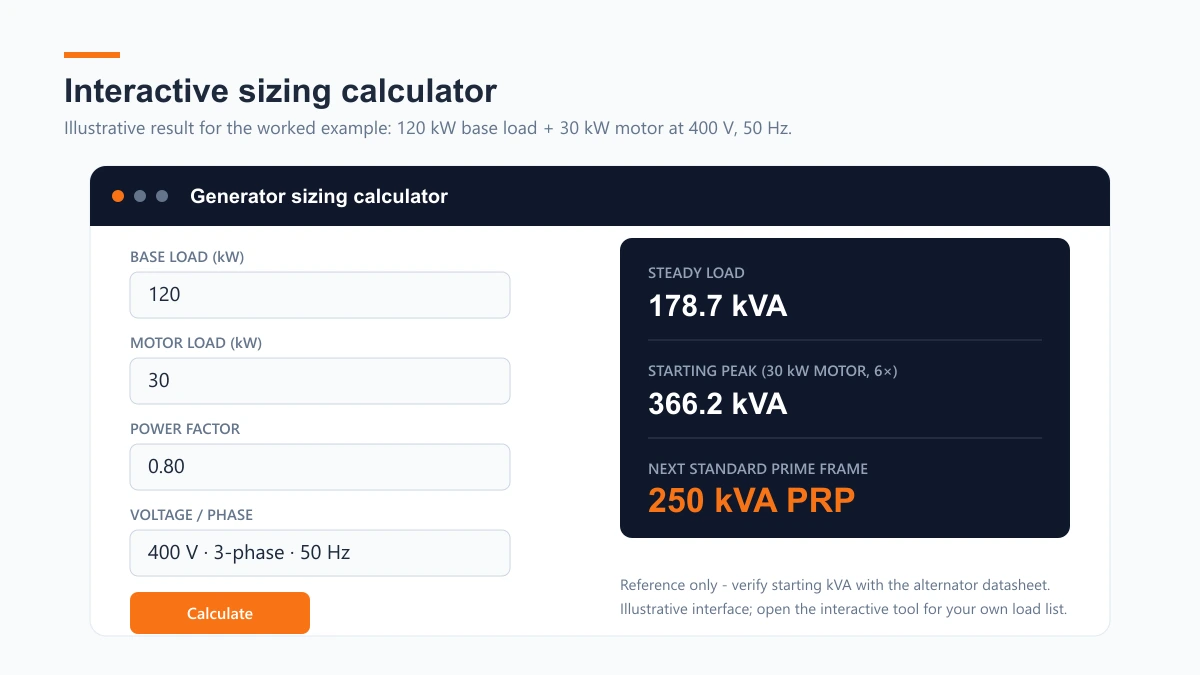
Interactive Power Engineering Tool
Planning a multi-load facility with complex motor inrush profiles? Model step loads, starting kVA and voltage dips with our calculator.
9. Seven Common Diesel Generator Sizing Mistakes
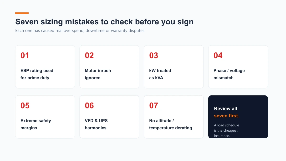
Even experienced facility managers can fall victim to common specification traps. Review these seven frequent sizing errors documented in engineering field audits from the Electrical Engineering Portal5.
- Substituting ESP Ratings for Prime Power Requirements: Purchasing a machine based on its Emergency Standby Power (ESP) numerical rating for an application requiring long, continuous outage operation. ESP carries zero overload capacity, a 200-hour annual operating limit, and a 24-hour average load factor cap of 70%. Continuous operation under heavy load leads to thermal shutdown and engine failure.
- Sizing Exclusively for Steady-State kW While Ignoring Motor Inrush: Selecting a generator set based solely on total running kilowatts without evaluating the starting kVA (SkVA) of electric motors. Direct-on-line motors draw 5 to 8 times their rated current during startup, causing severe transient voltage dips that trip circuit breakers and stall equipment.
- Confusing kW and kVA (Assuming Unity Power Factor): Assuming active power (kW) equals apparent power (kVA) across inductive loads. Sizing a generator for a 100 kW motor load at 0.80 PF requires a 125 kVA generator—not a 100 kVA generator. Ignoring power factor results in a 20% alternator capacity shortfall.
- Voltage and Phase Calculation Mismatch: Failing to account for phase current scaling. At identical kVA capacity, a single-phase system draws approximately three times the current of a balanced three-phase system. Connecting heavy single-phase loads to a three-phase generator without load balancing creates severe neutral currents and alternator overheating.
- Applying Extreme Safety Margins (Over-Sizing vs. Under-Sizing): Applying compounding, unverified safety margins that result in purchasing a massively oversized generator. Running a generator continuously below 30% of its rated capacity leads to unburned fuel accumulation, carbon buildup, lube oil dilution, and wet stacking. Conversely, omitting safety margins leaves zero headroom for future load growth.
- Neglecting Non-Linear Harmonics & VFD Crest Factors: Failing to account for harmonic current distortion generated by Variable Frequency Drives (VFDs), uninterruptible power supplies (UPS), and electronic LED drivers. Harmonic currents cause rotor heating and voltage waveform distortion, requiring alternators with 2/3 pitch windings and anti-harmonic excitation.
- Failing to Apply Environmental Altitude & Temperature Derating: Failing to derate generator output for site environmental conditions. Internal combustion engines lose oxygen density at high altitudes, and alternators experience reduced cooling efficiency at elevated ambient temperatures. Typical manufacturer reference conditions are up to 1,000 meters altitude and 40°C ambient temperature; confirm the actual rating basis with the engine manufacturer. Operating above these thresholds requires applying physical derating factors:
- Altitude Derating: typically ~3% to 5% power reduction per 300 meters above 1,000m.
- Temperature Derating: typically ~1% to 2% power reduction per 5°C ambient temperature above 40°C.
10. Frequently Asked Questions (FAQ)

How do I know what size diesel generator I need for my commercial facility?
Calculate total connected active power in kW, divide by your load power factor (PF = 0.80) for kVA, verify motor starting inrush current, and select a generator set whose Prime rating operates at an efficient 70% to 80% steady-state load factor.
What size generator do I need to power a 100 kW load?
At a standard commercial power factor of 0.80, a 100 kW active load requires 125 kVA of apparent power (kVA = 100 / 0.80). To operate near the optimal 75% load factor and accommodate motor starting surges, select approximately 160–170 kVA Prime Power (PRP) (a 150 kVA unit would run at an elevated ~83% steady-state load factor).
What is the technical difference between kVA and kW in generator ratings?
Kilowatts (kW) represent active or real power that performs useful work, whereas kilovolt-amperes (kVA) represent total apparent power, which combines active power and reactive power (kVAR). Generators and alternators are physically rated in kVA because their internal windings must handle total current flow regardless of system power factor (kW = kVA × PF).
How many Amps does a 200 kVA diesel generator supply?
On a standard 400V Three-Phase AC electrical system (at 0.80 PF), a 200 kVA diesel generator supplies a full-load running current of approximately 288.7 Amps (Amps = (200 × 1000) / (1.732 × 400)). On a 230V Single-Phase system, the same 200 kVA capacity delivers approximately 869.6 Amps.
Can I use an Emergency Standby Power (ESP) generator rating for continuous prime power duty?
No. Under ISO 8528-1 international standards, an Emergency Standby Power (ESP) rating is restricted to a maximum of 200 operating hours per year during emergency grid outages, with a 24-hour average load factor not exceeding 70% and zero allowable overload capacity. Operating an ESP-rated generator continuously under heavy prime load will cause overheating, automatic thermal tripping, premature engine wear, and warranty invalidation. Continuous duty requires a Prime Power (PRP) rated unit.
Why does my diesel generator trip its circuit breaker when large motors start?
Generator circuit breakers trip during motor starting because AC induction motors draw Locked Rotor Amperes (LRA)—typically 5 to 8 times their normal running current—at a very low power factor. This transient surge creates an instantaneous voltage dip and overcurrent condition. Mitigate starting trips by equipping large motors with soft starters or VFDs, staggering motor start sequences, or increasing alternator transient kVA capacity.
What is the 80% rule for generator sizing?
Continuous load should not exceed about 80% of a generator’s rated capacity (or a standard breaker’s nominal rating), leaving roughly 20% headroom for transient step loads and motor starting inrush. Confirm local code requirements with your electrical consultant.
What is the optimal load factor for a diesel generator?
Commercial diesels run most efficiently at about 70%–80% of their PRP rating, near the best BSFC point. Sustained operation below 30% risks wet stacking, carbon buildup and oil dilution. Confirm the operating profile with your engine manufacturer.
How do I convert kW to kVA for a commercial generator?
Divide active power by the load power factor: kVA = kW ÷ PF. At a typical commercial 0.80 PF, 100 kW equals 125 kVA (100 ÷ 0.80). Use the actual load PF where known.
Does altitude or ambient temperature affect generator capacity?
Yes. Standard commercial ratings typically apply up to 1,000 m altitude and 40°C ambient; beyond that, engines lose power with altitude and alternators cool less effectively. Derating rates are manufacturer-dependent — typically about 3%–5% per 300 m and 1%–2% per 5°C. Confirm with the engine datasheet.
11. Methodology & E-E-A-T Disclosure
Technical Methodology & Data Sources
The calculation workflows, rating definitions, and engineering recommendations in this guide are grounded in international technical standards, technical whitepapers, and field application engineering practices, including:
- ISO 8528-1:2018 & ISO 8528-5: Reciprocating internal combustion engine driven alternating current generating sets (Ratings & Transient Performance; defining ESP, PRP, LTP, and COP rating standards). Note that DCC/DCP is a manufacturer data-center classification aligned with the ISO 8528 PRP power level.
- IEEE Std 399 & IEEE Std 242: Recommended Practice for Industrial and Commercial Power Systems Analysis and Protection Coordination.
- Technical Whitepapers: Stamford-AvK Motor Starting Fundamentals (AGN 090), Kohler Power Systems Generator Transient Performance, Cummins Power Generation ISO Rating Guidelines, MTU Solutions Technical Ratings Documentation.
Engineering Advisory
This guide is published by generator-set manufacturing engineering specialists to support preliminary capacity planning. Final generator selection, protection coordination and single-line diagram approval should be reviewed by a qualified electrical consultant or locally licensed engineer before procurement.
Planning an electrical distribution upgrade or a new facility installation? Submit your single-line diagram (SLD) or equipment schedule to our engineering team for a direct factory engineering proposal: Engineering Consultation →
References
-
Electrical Installation Guide — Practical values of power factor for common commercial and industrial equipment loads. ↩︎
-
Logistics Cluster — ISO 8528 generating-set rating definitions for field and humanitarian power applications. ↩︎
-
Consulting-Specifying Engineer — Basic calculations for sizing generators and the impact of certain load types. ↩︎
-
Electrical Engineering Portal — Soft starter and reduced-voltage starting applications for industrial motors. ↩︎
-
Electrical Engineering Portal — Generator set selection guidance and common specification errors. ↩︎